
XK-M504E Airborne MIMO Mesh Radio
XK-M504E provides an airborne MIMO mesh node with two 5 W RF branches. Ethernet, RS232 and TTL connections bring network-video and serial terminals into the selected radio configuration for an unmanned or mobile system.
- 5 W × 2 RF output in the listed airborne configuration, with the supplied frequency band identified in the quotation.
- 12–26 V DC input; the manual lists operating current of 1–2.5 A at 16.8 V.
- 125 × 105 × 35 mm dimensions and 520 g radio weight define the listed installation form.
- Xingkai checks the node roles and connections, then quotes the radios and agreed accessories.
XK-M504E Airborne MIMO Mesh Radio Overview
XK-M504E carries IP and serial-terminal traffic through an airborne mesh-radio node. The two 5 W RF branches provide a distinct configuration for projects selecting that output level, alongside an RJ45 Ethernet interface, RS232 and two TTL UART interfaces.
Its listed 125 × 105 × 35 mm enclosure and 520 g device weight help define the radio installation. The 12–26 V DC input and current ratings give the electrical conditions for that configuration. Selecting the RF-output level does not by itself define the distance or video capacity of a deployed system. Its listed RF output differs from XK-M503E even though both manuals show the same enclosure dimensions and weight; model selection needs the radio configuration as well as the mechanical fit.
Technical Specifications
| Parameter | Listed configuration |
|---|---|
| RF output | 5 W × 2; airborne configuration |
| DC input | 12–26 V |
| Operating current | 1–2.5 A at 16.8 V |
| Standby current | 0.3–0.5 A at 16.8 V |
| Dimensions | 125 × 105 × 35 mm |
| Radio weight | 520 g |
| Mounting | 4 mounting holes |
| RF interfaces | 2 × SMA |
| Network interface | 1 × RJ45 Ethernet, 100/1000Base-T |
| Serial interfaces | 1 × RS232; 2 × TTL UART |
| Management | Web-based GUI; API/SNMP interface |
Connections and Integration
M504E provides one RJ45 network connection, one RS232 interface and two TTL UARTs. List each network and serial terminal so Xingkai can specify the J30 harness branches and electrical levels for the supplied node, keeping any video-interface equipment explicit.
Identify the endpoint or relay role and required antenna arrangement. The manual requires the antenna or appropriate load to be connected before applying power; switch power off before antenna replacement. The supplied J30 connection drawing governs the harness, not another model’s pinout.

Configure and Order Your Mesh Nodes
Tell Xingkai the required airborne-node quantities and why the 5 W × 2 configuration is being selected. Provide the terminal connections and available supply so the quotation can define the radio and accessory scope.
Confirm the supplied configuration, quantities and delivery terms before ordering. Xingkai supplies and dispatches according to the agreed order.
Send the node roles, terminal connections, available supply and radio quantities.
Xingkai checks the model and configuration, then quotes the required radios and accessories.
Agree on the configuration, quantities and delivery terms.
Xingkai supplies and ships according to the confirmed order.
FAQs
Matching dimensions and weight do not establish a replacement. The two models have different listed RF-output levels. Provide the installed model, frequency configuration and network settings so Xingkai can check the intended replacement and supplied accessories.
No. The 1–2.5 A entry at 16.8 V applies to the listed radio configuration. The platform budget also needs the camera, encoder, computer and other equipment sharing the supply. List those loads separately for the intended installation.
List both Ethernet devices and their combined traffic alongside any RS232 or TTL terminals. The M504E manual identifies one RJ45 connection, so do not plan two direct network-device connections from the serial-port count. Request the network arrangement and any separate connecting equipment required, while keeping the one-RS232/two-TTL allocation distinct. The resulting equipment list should identify the devices and cables needed without treating a gigabit port rating as guaranteed wireless capacity.
State endpoint and relay node counts, traffic directions, video-stream rates and the deployment conditions. Xingkai uses those requirements when specifying the network configuration. A listed relay function alone is not a guaranteed multi-hop video capacity.
The connectors identify the radio interface, rather than the supplied antenna type or gain. Specify the required antenna arrangement for the selected band and installation. Xingkai identifies the antennas and cables included in the quotation before the supply scope is confirmed.
Compare Related Models
Airborne mesh node with two 2 W RF branches and a listed 12–26 V DC input.

Mesh video and data radio with Ethernet, UART and SBUS interfaces for different terminal connections.

Vehicle mesh radio with two 20 W RF branches; compare the 18–32 V DC configuration and its electrical load.
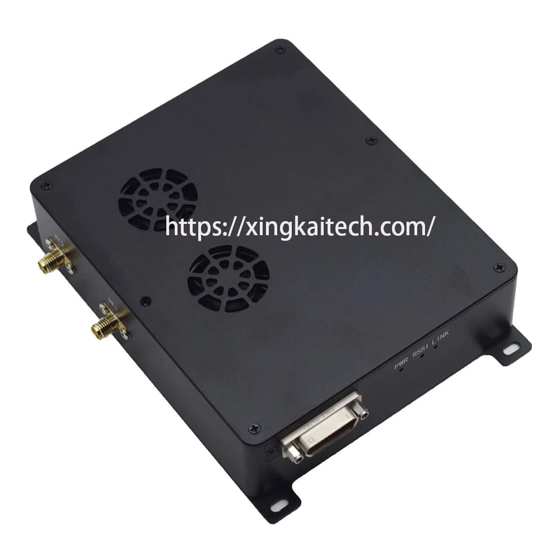
Appearance reference; the supplied hardware configuration is confirmed in the quotation.
Compare XK-M372 for projects considering a 5 GHz network node.
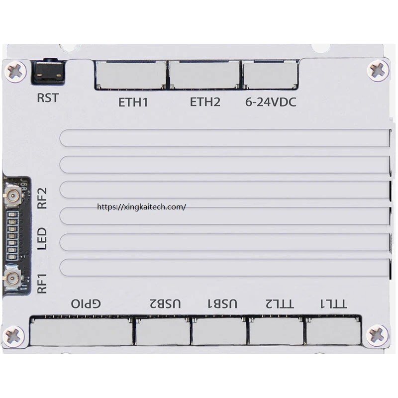
Interface detail shown for reference. The pictured label is not a power specification for the supplied configuration.
Request a Configuration Quote for XK-M504E
Send the node roles and quantities, terminal interfaces, available DC supply and intended antenna layout. Xingkai will check the XK-M504E configuration and provide a radio and accessory quotation.