
XK-M413E Airborne Mesh Radio
XK-M413E gives airborne network, telemetry and remote-control equipment a shared mesh radio node. The listed 1420–1530 MHz configuration combines Ethernet, serial and SBUS connections with centreless point-to-point, point-to-multipoint and mesh relay modes.
- Ethernet, UART and SBUS connections carry network traffic and control data through the selected radio configuration.
- Two adjustable RF channels are rated at 33 dBm each for the listed airborne model.
- 12–28 V DC input, with a standard 16.8 V input, gives a stated supply range for platform selection.
- 135 × 90 × 27.5 mm and device weight ≤350 g support space and weight comparisons for the installation.
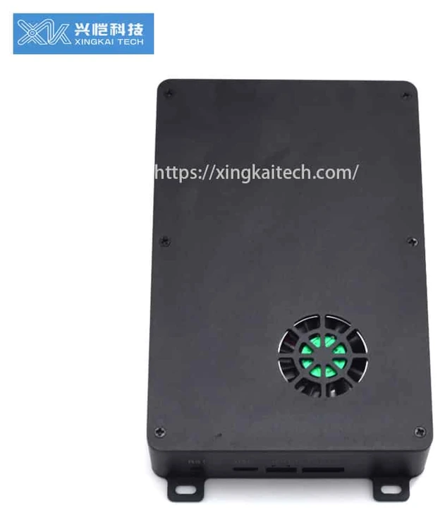
XK-M413E exterior shown; supplied enclosure and interfaces are specified in the quotation.
XK-M413E Airborne Mesh Radio Overview
XK-M413E is an airborne mesh radio for companies connecting network payloads, serial telemetry and SBUS control equipment. Its distributed centreless network supports direct links, point-to-multipoint operation and relay or mesh layouts, providing connection choices for different arrangements of air and ground nodes.
The listed 1420–1530 MHz version uses a 12–28 V DC supply, with a standard input of 16.8 V. Electrical power consumption is specified as ≤20 W at 33 dBm RF output. Use that stated condition alongside the device dimensions and weight when assessing the platform installation.
Xingkai specifies the radio configuration around the required terminal interfaces and communication layout. The quotation identifies the radio units, antennas and cables supplied. Confirm that configuration and the unit quantities before ordering, especially when adding a node to equipment already in use.
Technical Specifications
Listed 1420–1530 MHz airborne configuration. Interface levels and supplied accessories are specified for the order.
| Parameter | Listed configuration |
|---|---|
| Frequency | 1420–1530 MHz; listed configuration |
| RF output | 2 × 33 dBm; adjustable |
| DC input | 12–28 V DC; standard input 16.8 V |
| Electrical consumption | ≤20 W at 33 dBm RF output |
| Dimensions | 135 × 90 × 27.5 mm |
| Device weight | ≤350 g |
| Channel bandwidth | 3 / 5 / 10 / 20 MHz |
| Modulation | QPSK / 16QAM / 64QAM |
| Data/control connections | Ethernet; UART TTL/RS232 and RS232/RS485/RS422; SBUS |
| Communication protocol | IEEE 802.3; transparent serial data |
| Networking | Distributed centreless point-to-point, point-to-multipoint, relay and mesh |
| Encryption | AES128; listed configuration |
| Operating temperature | −30 to +60 °C |
| Storage temperature | −40 to +75 °C |
Connections and Integration
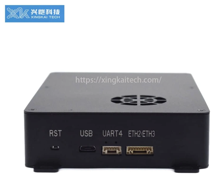
USB/UART enclosure shown as an appearance reference; supplied enclosure and interfaces are specified in the quotation.
Ethernet carries IP traffic, while UART connections serve serial equipment and SBUS carries remote-control data. The listed configuration provides Ethernet and serial connections with TTL/RS232 and RS232/RS485/RS422 choices; the electrical interface must match the connected terminal.
Xingkai checks those connections and the intended relay or mesh layout when specifying the radio configuration. AES128 is the listed table entry; any different encryption configuration must be identified separately in the quotation.
Configure and Order Your Radio
Specify the M413E’s network, telemetry and SBUS tasks alongside the 12–28 V supply arrangement, with standard input listed as 16.8 V. The quotation records the selected terminal interfaces and radio configuration.
Send the node layout and quantities, Ethernet equipment, UART terminals and any SBUS control requirement. Name the TTL/RS232 or RS232/RS485/RS422 interface needed by each terminal, the available supply and the required AES128 configuration.
Xingkai checks the M413E power and interface selections, then quotes the radio version, antennas and terminal harnesses. The equipment list identifies the chosen serial levels and SBUS connections rather than treating all data/control cables as interchangeable.
Agree on the supplied configuration, quantities and delivery terms before proceeding.
Xingkai supplies and ships according to the confirmed order.
FAQs
No. The interface entry describes a supported signal type, not universal flight-controller compatibility. Provide the controller model, required electrical levels and the planned connection. Xingkai checks the proposed radio interface and harness arrangement before quoting. Compatibility must be confirmed for the selected controller and configuration rather than inferred from the presence of an SBUS connection.
The listed connections are Ethernet, UART and SBUS. They do not establish an included HDMI or SDI input. Send the camera model and output type so the required network-video or encoder arrangement can be identified. Any separate video-interface equipment should appear explicitly in the proposed configuration and supply list alongside the radio units.
The listed technical table identifies AES128 for this configuration. Other settings or capabilities should not be assumed from a general product-family description. Provide the installed nodes’ model and firmware details together with the required security settings. Xingkai checks the proposed configuration; the nodes must use compatible settings for the intended network.
A radio single-hop figure does not include every part of a camera-to-display system. Encoding, network traffic, additional relay hops and decoding can affect the complete path. Describe the video and control task, the terminal equipment and the proposed layout when requesting a configuration. A project requirement for end-to-end delay needs assessment for that complete arrangement.
Show where each telemetry or control signal starts and ends, and name the interface at both ends. The M413E lists UART electrical choices and SBUS as separate connections; identical radio models do not establish identical terminal cables at the aircraft and ground station. Request a harness line for each required terminal connection, with its endpoint identified. Count relay-only radios separately from radios that need local telemetry or SBUS terminal cables.
Compare Related Models

Black 2 W × 2 airborne configuration with a DB15 connection record.
Black enclosure reference; supplied version is specified in the quotation.

Compare the 5 W × 2 airborne radio configuration and confirm the supplied interface and connector arrangement.

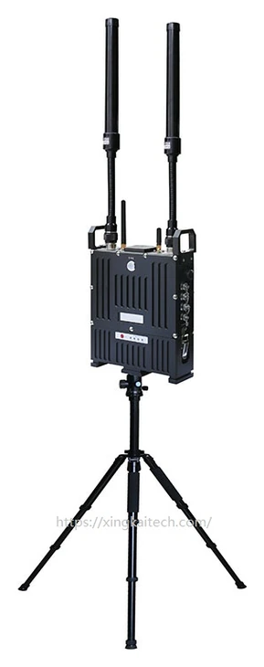
Manpack and airborne mesh node with network, TTL and PTT connections.
Shown antennas and tripod are specified in the quotation.
Request a Configuration Quote for XK-M413E
Tell us which equipment and nodes your XK-M413E network needs to connect. Include the operating band, terminal interfaces, power arrangement and required radio quantities. Xingkai will check the configuration and provide a quotation identifying the radio units and accessories.