
XK-CF01 Multirotor Drone Platform
Build an imaging-equipment brief around the CF01’s 1600 mm multirotor platform. Its documented equipment choices include photoelectric pods, multispectral cameras and mapping cameras, letting you specify the sensor needed for the task while identifying the flight-platform and mission items separately in the quotation.
- Multirotor platform for a proposed imaging or mapping-equipment configuration.
- Toray 3K carbon fiber shell with an internal-pressure forming process.
- 1600 mm symmetrical wheelbase and 600 mm height identify the platform envelope.
- Photoelectric pods and imaging sensors can be considered for the platform, with fit and supply scope checked for the configuration.
XK-CF01 Multirotor Drone Platform Overview
XK-CF01 provides a multirotor platform around which businesses can discuss imaging or mapping equipment. Photoelectric pods, multispectral and mapping cameras, and a video link can be considered for the platform. Their fit and inclusion depend on the selected configuration.
A Toray 3K carbon fiber shell and 1600 mm symmetrical wheelbase define the listed structure and size. The 3500 g shell-weight entry refers to the shell alone. It is not a complete aircraft weight or an allowance for a mission payload.
Xingkai checks the proposed equipment configuration before quoting. Identify the camera or sensor, mounting and control arrangement so the supplied platform and accessories are clearly specified.
Technical Specifications
| Parameter | Model reference |
|---|---|
| Aircraft type | Multirotor platform |
| Shell material | Toray 3K carbon fiber |
| Shell forming process | Internal-pressure forming |
| Symmetrical wheelbase | 1600 mm |
| Aircraft height | 600 mm |
| Shell weight | 3500 g; shell only |
Configure the Imaging Payload and Data Path
Choose the CF01 mission equipment by the required image: photoelectric observation, multispectral capture or mapping. Its 1600 mm wheelbase and 600 mm height define the overall platform envelope; they do not provide the sensor’s mounting dimensions. Provide the selected camera and mount together, including their combined mass, clearance, power and control/data connections.
Identify which equipment supplies the ground view or collected data. Specifying that path alongside the flight-platform and battery arrangement makes the imaging installation and its supply responsibilities explicit before procurement.

Define the CF01 Platform and Imaging Supply Scope
State whether your request concerns the shell, an assembled flight-platform configuration or a platform with selected imaging equipment. Xingkai checks the requested scope and identifies the agreed structure, propulsion, batteries, controls and mission items in the quotation, with customer-supplied equipment marked separately.
Identify the required scope and camera/pod, installed sensor-and-mount mass, power/data connections and ground-output needs. Send the proposed propulsion/battery and control equipment, identify customer-supplied parts, and state quantities and mission duration.
Xingkai checks the proposed imaging installation against the 1600 mm platform and requested assembly scope. The quote identifies the supplied shell/platform components, agreed propulsion and battery arrangement, controls, selected mission equipment and required mounting/interface items.
Agree the exact supplied and customer-supplied items, installed-weight basis, sensor interfaces and battery arrangement. Confirm the mission-duration requirement for that configuration, then agree quantities and delivery terms; the 3500 g shell entry is not the complete supplied-aircraft weight.
Xingkai arranges supply and dispatch of the agreed CF01 configuration and listed equipment according to the confirmed order.
FAQs
No. It is identified as shell weight. A complete aircraft also has propulsion, power, control and other installed equipment, with the exact arrangement depending on the configuration. Ask for the weight basis of the proposed supplied assembly before using the shell entry for vehicle loading or flight-system planning.
No. That entry concerns the shell, not an established flight-payload allowance. Do not select a camera or pod by subtracting the 3500 g shell weight from it. Provide the complete sensor/mount mass and other installed equipment, then request the allowable load and aircraft-weight basis for the proposed propulsion and battery configuration. Those agreed configuration figures are needed before committing to a heavier imaging package.
The published entry pairs 91 minutes with four 25000 mAh batteries, but does not identify the carried payload or complete operating conditions. It therefore does not establish that duration for your selected camera, pod or mount. Send the installed mission load, proposed battery arrangement and required working duration. Request a configuration-specific duration basis before selecting batteries or committing the mission plan; the reference is not a four-battery supply list.
Identify which outputs the chosen CF01 camera or sensor produces and when they must reach the user: a live operator view, collected imaging data after the mission, or both. Give the camera’s output/interface details and any existing ground equipment. Request the required video/data path and storage or transfer items separately for that workflow. A mention of a mapping camera or video link does not define how every selected sensor delivers its results.
Identify both as customer-supplied items and state whether the mount is already fixed to the sensor. Provide a drawing showing their combined mounting points and the cables leaving the assembly. Ask Xingkai to distinguish retained hardware from any additional mounting or interface parts in the proposed configuration; including a sensor in the brief does not transfer its supply responsibility.
Compare Related Models
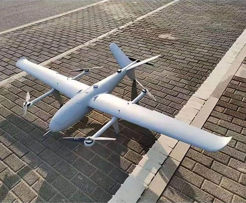
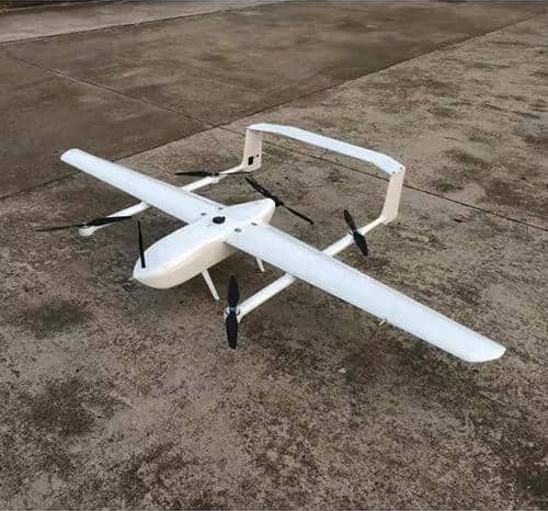
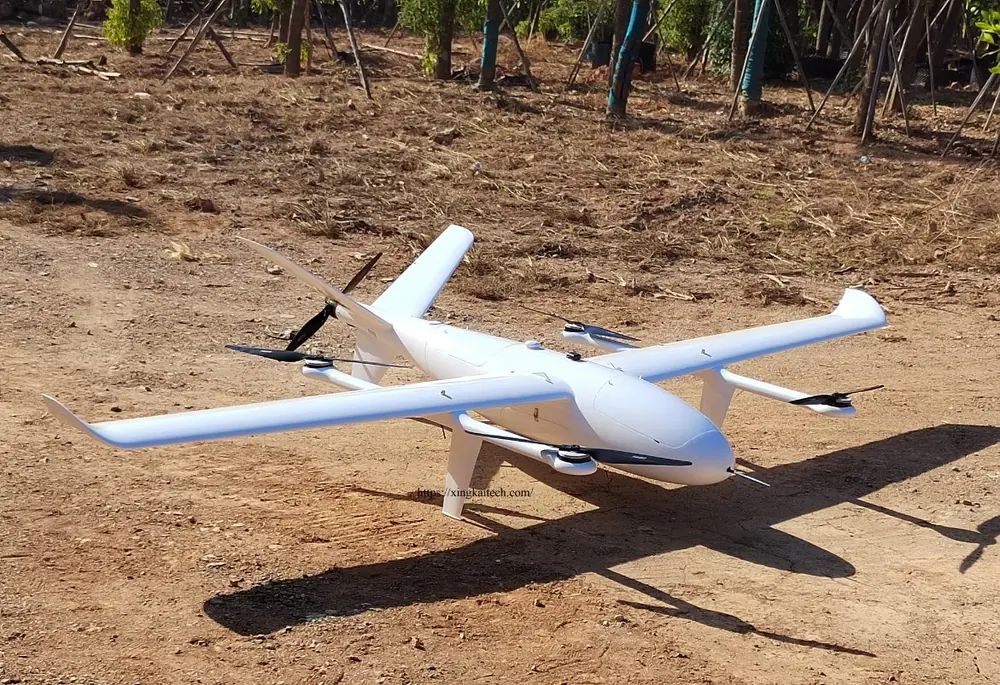
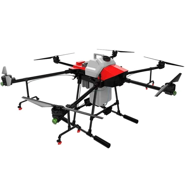
30 L spraying model with changeable spreading equipment; confirm the attachment supplied.
Request a Configuration Quote for XK-CF01
Send the imaging task, camera or sensor, installed equipment and mounting requirements, control arrangement and quantities for XK-CF01. Identify any equipment you will provide and the items you need supplied. Xingkai will check the proposed configuration and provide a quotation.