
XK-F413E Wireless Video and Data Link
For a platform link that needs network video, serial telemetry and SBUS control, XK-F413E brings the three data paths onto one radio system. Xingkai supplies the air and ground configuration around your terminals and planned communication layout.
- UART with TTL, RS232 or RS485, together with SBUS, gives you interface choices for existing telemetry and control equipment.
- Point-to-point and point-to-multipoint relay configurations let you plan the radio system around one platform or several endpoints.
- 12–28 V DC input, nominal 16.8 V, and consumption of ≤20 W at 33 dBm provide electrical conditions for planning the platform supply.
- A 135 × 90 × 27.5 mm enclosure and device weight of ≤350 g make the radio’s installation requirements clear before ordering.
XK-F413E Wireless Video and Data Link Overview
XK-F413E serves projects where video, flight-control data and remote-control data need to share a platform-to-ground link. Ethernet traffic and transparent serial or SBUS transmission support the equipment paths without requiring separate radio products for each data type.
The listed configuration uses a nominal 16.8 V supply within a 12–28 V DC input range. Its RF-output entry is 2 × 33 dBm, adjustable; the electrical-consumption rating is ≤20 W at the stated 33 dBm condition. Use the consumption rating for the power budget and retain space for the enclosure, connectors and antenna cabling.
Xingkai checks the terminal interfaces and link layout, then specifies the radio units and accessories in a quotation. This identifies the supplied configuration and quantities, so your air and ground equipment can be ordered against the same requirements.
Technical Specifications
These entries describe the listed 1.4 GHz configuration. The quotation identifies the supplied frequency configuration, radio units, antennas and cables.
| Parameter | Listed configuration |
|---|---|
| Power input | 12–28 V DC; nominal 16.8 V |
| Power consumption | ≤20 W at 33 dBm |
| RF output power | 2 × 33 dBm, adjustable |
| Frequency range | 1420–1530 MHz |
| Channel bandwidth | 3 / 5 / 10 / 20 MHz |
| Radio dimensions | 135 × 90 × 27.5 mm |
| Device weight | ≤350 g |
| Modulation | OFDM |
| Data/control interfaces | UART (TTL/RS232/RS485), SBUS |
| Communication protocol | IEEE 802.3; transparent serial data |
| Link modes | Point-to-point; point-to-multipoint relay |
| Antenna references | Air unit: 3.5 dBi; ground unit: 9 dBi |
| Rated operating temperature | −30 to +60 °C |
| Rated storage temperature | −40 to +75 °C |
| Security and channel operation | AES128 encryption; adaptive frequency hopping |
Connections and Integration
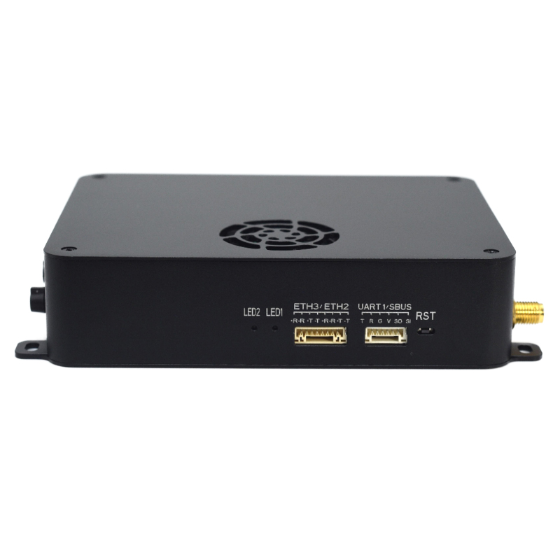
F413E provides connections for up to three network devices, three serial ports and one SBUS path. A network camera can therefore be planned alongside separate flight-control and payload serial terminals. Identify the TTL, RS232 or RS485 level required for each UART connection; the ground station uses serial or UDP/TCP to exchange data.
The nominal 16.8 V arrangement operates within 12–28 V DC, with ≤20 W consumption at 33 dBm. Allow for that radio load beside the camera and control equipment when defining the platform supply.

Configure the F413E Camera and Control-Terminal Map
Define which network devices, serial terminals and SBUS control path the F413E must connect. Xingkai quotes the listed 1420–1530 MHz configuration, selected bandwidth and UART electrical connections, with the RF/antenna arrangement and endpoint accessories specified for your installation.
List each network camera/device and flight-control or payload serial terminal with its TTL, RS232 or RS485 requirement. Include any SBUS connection, ground receiving equipment, concurrent traffic, channel bandwidth, actual supplies, endpoint roles and quantities.
Xingkai checks the terminal map against the network/serial resources and requested endpoint arrangement. The quote identifies the 1420–1530 MHz radio, selected 3/5/10/20 MHz bandwidth, electrical connections and agreed RF/antenna, data-cable and interface-equipment scope.
Confirm the 12–28 V DC arrangement with ≤20 W radio consumption at 33 dBm and space for the 135 × 90 × 27.5 mm enclosure. Agree the supplied 2 × 33 dBm RF configuration, endpoint accessories, quantities and delivery terms.
Xingkai supplies and ships the confirmed F413E configuration, endpoint quantities and listed accessories according to the agreed order.
FAQs
XK-F413E connects network video through Ethernet. For a camera with HDMI or SDI output, send the camera model and output type so Xingkai can check the network-video and encoding arrangement. Specify any encoder or interface equipment separately in the proposed supply scope; do not assume that a video-output connector on the camera is a direct radio input.
The F413E functional entry describes connected network devices, not an established maximum count of wireless air units. For an expansion, identify the retained ground/central unit’s full version and settings, the added radio roles and how the station must receive their camera or payload data. Request the proposed multipoint arrangement and added-unit configuration explicitly. Do not order extra air units by treating a network-port count as the radio system’s endpoint capacity.
Do not budget the selected channel bandwidth as a separate allocation for every endpoint. The system description identifies shared operation for the central and slave nodes. State the number of endpoints and the video and data loads that must run together so Xingkai can check the proposed layout. Channel bandwidth alone does not establish the application throughput of each endpoint.
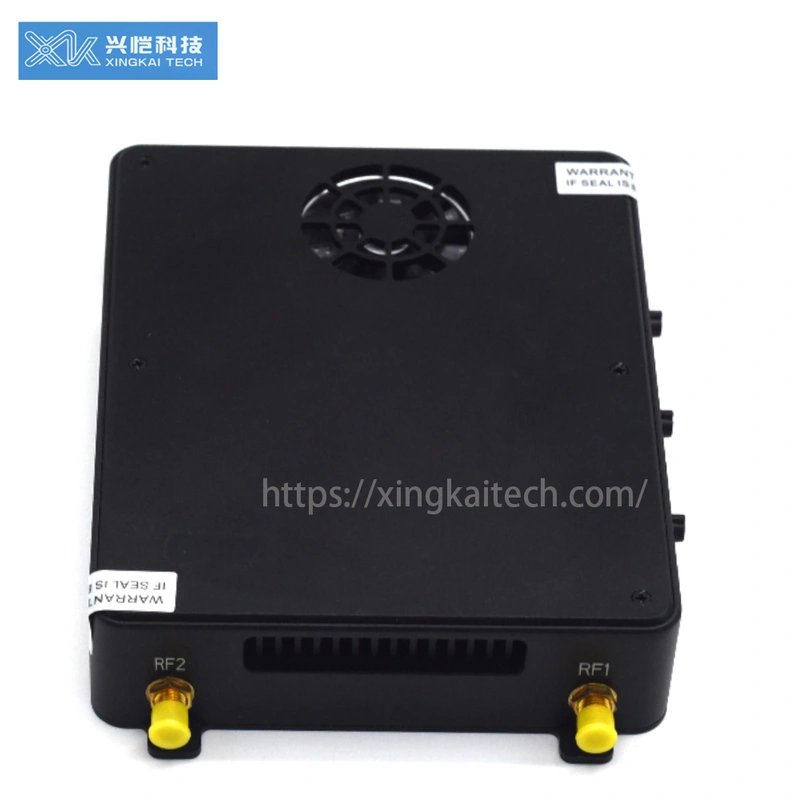
The F413E references differ: 3.5 dBi on the air side and 9 dBi on the ground side. Provide each existing antenna’s model, supported frequency, lead/connector details and mounting position for the selected 1420–1530 MHz configuration. Identify the moving platform’s clearance separately from the ground arrangement, then have retained and replacement antenna items distinguished. Gain or a matching connector alone does not establish that one antenna suits both roles.
Keep platform and ground-end installation lists separate. On the platform list, count every radio, antenna, cable and mounting component carried onboard, then add their individual weights for the installed assembly. The device-weight entry describes the radio rather than that assembly. Confirm which components your platform will carry and their weights before allocating the complete payload budget.
Compare Related Models

Compare its smaller 96 × 78 × 19 mm enclosure and ≤190 g device weight where installation space guides selection.

Consider the larger 175 × 130 × 30 mm enclosure and ≤810 g device weight when planning another radio configuration.
Compare its 115 × 92 × 28 mm footprint; request electrical requirements for the exact supplied version.
Discuss the required F403E configuration and its terminal arrangement before comparing supply scope and accessories.
Request a Configuration Quote for XK-F413E
Send the camera, flight-control and payload-terminal map for your F413E link, including each required serial electrical level. Include the ground equipment, bandwidth, actual supplies and endpoint quantities. Xingkai will check the listed 1.4 GHz configuration and quote the radios and agreed antenna/connecting scope.