
XK-F404E Wireless Video and Data Link
XK-F404E combines video, telemetry and remote-control data for projects able to accommodate a larger radio and its power load. Xingkai specifies the air and ground equipment around your platform interfaces and intended link layout.
- Network data, UART telemetry and SBUS control share the wireless link, bringing the camera and control paths into one radio configuration.
- The listed 2 × 37 dBm adjustable RF-output configuration gives you an output specification to assess alongside antenna and installation requirements.
- 12–28 V DC input, nominal 12 V, with consumption of ≤35 W at 37 dBm defines the electrical condition for your platform power budget.
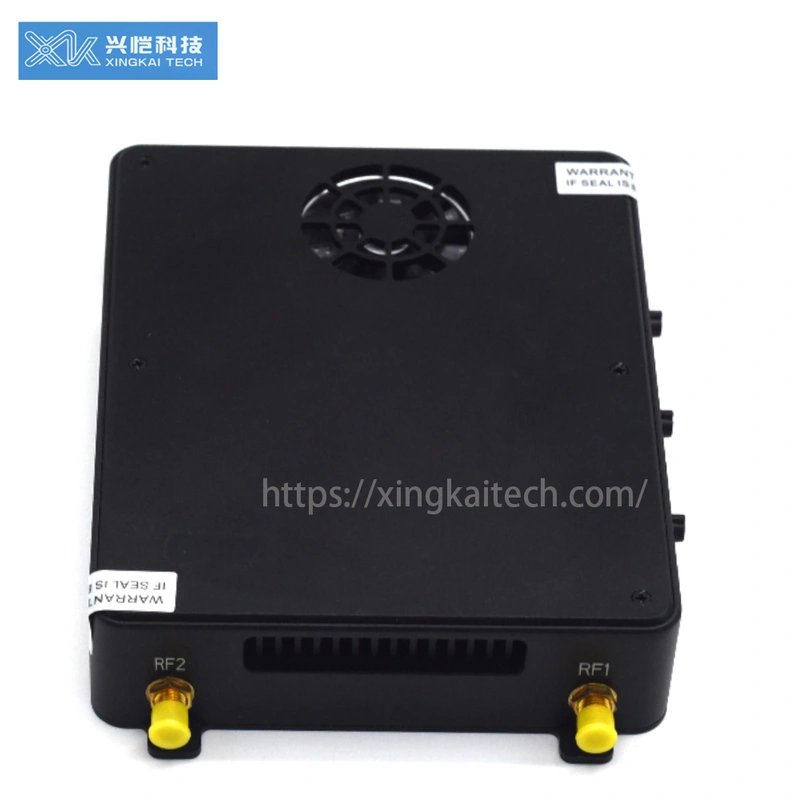
- 175 × 130 × 30 mm and device weight of ≤810 g make the installation and payload requirements explicit for larger platforms.
XK-F404E Wireless Video and Data Link Overview
XK-F404E brings IP video, transparent serial data and remote-control data onto one wireless link. Point-to-point and point-to-multipoint relay configurations allow the radio arrangement to follow your platform and ground-end requirements rather than treating every installation as a fixed pair.
This model calls for a larger installation budget: the radio is 175 × 130 × 30 mm with device weight of ≤810 g. Its listed electrical consumption is ≤35 W at 37 dBm, distinct from the 2 × 37 dBm adjustable RF-output entry. Compare the enclosure, carried components and available supply before selecting this configuration.
Xingkai checks the interfaces and communication layout, then quotes the required radio units and accessories. The confirmed configuration, quantities and delivery terms define the supply scope; RF output alone does not establish operating distance or application performance.
Technical Specifications
The table describes the listed 1.4 GHz configuration. Antenna entries are configuration references; supplied radio units and accessories are identified in the quotation.
| Parameter | Listed configuration |
|---|---|
| Power input | 12–28 V DC; nominal 12 V |
| Power consumption | ≤35 W at 37 dBm |
| RF output power | 2 × 37 dBm, adjustable |
| Frequency range | 1420–1530 MHz |
| Channel bandwidth | 3 / 5 / 10 / 20 MHz |
| Radio dimensions | 175 × 130 × 30 mm |
| Device weight | ≤810 g |
| Modulation | OFDM |
| Data/control interfaces | UART (TTL/RS232/RS485), SBUS |
| Communication protocol | IEEE 802.3; transparent serial data |
| Link modes | Point-to-point; point-to-multipoint relay |
| Antenna references | Air unit: 3.5 dBi; ground unit: 16 dBi |
| Rated operating temperature | −30 to +60 °C |
| Rated storage temperature | −40 to +75 °C |
| Security and channel operation | AES128 encryption; adaptive frequency hopping |
Connections and Integration
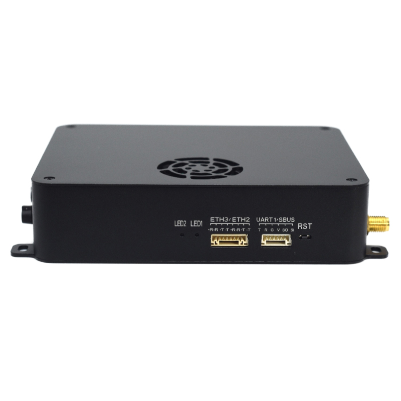
F404E supports up to three network-device connections, three serial ports and one SBUS path. This gives a platform’s network-video and separate telemetry/payload terminals defined connection resources. Specify TTL, RS232 or RS485 for the required UART connections; ground equipment exchanges data through serial or UDP/TCP.
Plan those terminals within the listed 1420–1530 MHz configuration and selected channel bandwidth. For multipoint relay operation, identify the traffic that must run together: added endpoints share the working bandwidth in one direction rather than receiving independent capacity.

Configure the F404E Payload and Terminal Arrangement
Provide the platform’s power and installation allowance alongside its network and serial-terminal requirements. Xingkai quotes the listed 1.4 GHz F404E configuration, selected bandwidth and electrical connections, with the RF/antenna arrangement and endpoint accessories identified for the order.
Send the network devices, individual telemetry/payload serial terminals and electrical levels, plus any SBUS connection. Include concurrent traffic, requested bandwidth, endpoint roles, actual supply ranges, mounting/payload allowance and quantities.
Xingkai checks the terminal map against the network/serial resources and 1420–1530 MHz configuration. The quotation identifies the selected 3/5/10/20 MHz bandwidth, radio roles, UART connections and agreed antennas, RF/data cables and interface-equipment scope.
Check the 175 × 130 × 30 mm, ≤810 g device against the platform allowance and the 12–28 V DC supply against ≤35 W consumption at 37 dBm. Agree the supplied 2 × 37 dBm RF arrangement, accessories, quantities and delivery terms.
Xingkai supplies and ships the confirmed F404E configuration, endpoint quantities and listed accessories according to the agreed order.
FAQs
Reconsider it if the complete onboard assembly or available supply cannot accommodate the ≤810 g radio, its accessories and the listed ≤35 W load at 37 dBm. The 2 × 37 dBm RF entry does not remove those installation requirements or establish achieved distance. Send the payload and supply limits with the actual video/control task; compare a feasible alternative configuration rather than selecting this radio solely by the larger RF figures.
Compare your platform supply with the listed 12–28 V DC input requirements before fixing the power arrangement. If a converter is needed, identify it separately from the radio in the installation and supply list. Provide the available supply details so Xingkai can check the proposed configuration; do not assume that conversion equipment is built into the radio or included in the order.
Make an onboard installation list separate from the ground equipment. Add each carried radio, antenna, cable and mounting component to that list and sum their weights. The ≤810 g entry is device weight, so it is not the complete assembly total. Confirm the selected components and their weights before allocating the platform payload budget or comparing alternative radio installations.
XK-F404E uses a network interface for IP video. For an HDMI or SDI camera, provide its output type and model so Xingkai can check the encoding and network-video path to the radio. Identify any encoder or interface equipment as a separate part of the proposed configuration and supply scope, rather than assuming that the radio accepts the camera connector directly.
Identify the terminal assigned to each required serial port, its TTL/RS232/RS485 level and serial settings. F404E lists three serial ports, but that does not define one universal connector, pinout or electrical form for every supplied connection. Send the existing harness details and required device operations. Have the retained wiring and any changed leads identified individually so the order matches the terminal map rather than only a total cable quantity.
Compare Related Models

Compare its 135 × 90 × 27.5 mm enclosure and ≤350 g device weight where a smaller installation is required.

Consider its 96 × 78 × 19 mm enclosure and ≤190 g device weight alongside the required interfaces and supply.
Compare its 115 × 92 × 28 mm footprint and confirm the electrical requirements for the proposed version.
Ask about the required F403E configuration and compare its radio and accessory scope with your intended installation.
Request a Configuration Quote for XK-F404E
Send your F404E platform’s mounting/payload allowance, actual supply and network/serial-terminal map. Include the required bandwidth, concurrent endpoint tasks and radio quantities. Xingkai will check the listed 1.4 GHz configuration and quote the selected radios, RF connections and installation accessories.