
XK-304E Wireless Video and Data Link
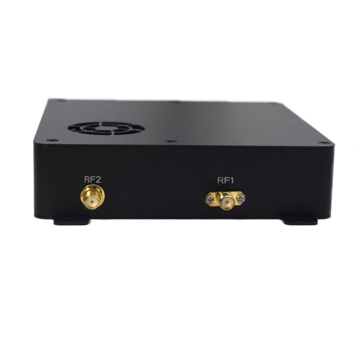
Single-housing appearance reference. The supplied -100 configuration, endpoint roles and accessories are specified in the quotation.
Build a wireless connection for network video and control equipment with the listed XK-304E-100 configuration. Ethernet, serial data and SBUS support different signals within the same link, while the selected radio band and endpoint arrangement define the quotation.
- Network, UART and SBUS connections bring video, telemetry and control equipment onto one radio system.
- 3 / 5 / 10 / 20 MHz bandwidth choices let the configuration follow the project's spectrum and traffic requirements.
- Point-to-point and point-to-multipoint relay modes support different endpoint layouts.
- The listed 12–25 V DC input and ≤20 W consumption at 37 dBm provide a defined starting point for the installation power budget.
XK-304E Wireless Video and Data Link Overview
XK-304E is offered here in the listed -100 configuration for companies connecting network-video equipment, telemetry and remote-control terminals. It carries the connected equipment's data across a wireless link; camera encoding and the operator application are separate parts of the system. Network and serial connections give platform builders a way to combine those signals without treating the radio as a camera or flight controller.
The configuration includes selectable bandwidths, a quoted frequency-band arrangement and point-to-point or point-to-multipoint relay operation. Xingkai checks the endpoint quantities, terminal interfaces and accessory requirements, then identifies the supplied model designation and configuration in the quotation. Use that agreed configuration for installation and ordering; the parameter table below describes the listed XK-304E-100 offering.
Technical Specifications
| Parameter | Listed XK-304E-100 configuration |
|---|---|
| Power input | 12–25 V DC; nominal 22 V |
| Power consumption | ≤20 W at 37 dBm RF output |
| Modulation | OFDM |
| Data/control interfaces | UART (TTL/RS232), SBUS; Ethernet described in product functions |
| Listed frequency configurations | 800 MHz / 1.4 GHz / 2.4 GHz; supplied band specified in the quotation |
| Bandwidth choices | 3 / 5 / 10 / 20 MHz |
| Listed maximum uplink channel rate | 30 Mbps; operating conditions not specified |
| Listed maximum downlink channel rate | 26 Mbps; operating conditions not specified |
| Listed transmission latency | ≤15 ms; measurement scope not specified |
| RF output power | ≤37 dBm; adjustable |
| Air-unit antenna reference | 3.5 dBi |
| Ground-unit antenna reference | 16 dBi |
| Communication protocol | IEEE 802.3; transparent serial data |
| Link modes | Point-to-point; point-to-multipoint relay mode |
| Encryption functions | AES128 / AES256 |
Connections and Integration
Single-housing appearance reference. The supplied -100 configuration, endpoint roles and accessories are specified in the quotation.
Connect network-video equipment through Ethernet and select the UART electrical interface as TTL or RS232 for the connected terminal. SBUS carries the selected control data. At the ground end, the serial connection or UDP/TCP network connection exchanges data with the station; this separates the radio connection from the camera's encoding and the operator software.
Xingkai identifies the selected frequency configuration, endpoint roles and cable or antenna requirements in the quotation. The listed 800 MHz, 1.4 GHz and 2.4 GHz entries are configuration choices, rather than a promise that every supplied radio operates in all three bands.

Specify the 304E-100 Band, Traffic and Power Arrangement
The quotation identifies the supplied XK-304E-100 configuration: operating band and bandwidth, terminal connections, radio quantities by role and required accessories. Provide the actual supply range at each end and the video, telemetry and control traffic that will share the link.
List the network-video source, stream bitrate and concurrent telemetry/control traffic. Identify UART TTL or RS232 and any SBUS terminals, requested 800 MHz, 1.4 GHz or 2.4 GHz band, channel bandwidth, actual DC supply range and quantities for each endpoint role.
Xingkai checks the requested band, 3/5/10/20 MHz bandwidth and terminal arrangement against the proposed traffic. The quotation identifies the supplied -100 radio configuration, unit quantities and accessories, with any external video encoder separately listed.
Confirm that each radio supply remains within 12–25 V DC and allows for the listed ≤20 W radio consumption at 37 dBm. Agree the band, bandwidth, UART level, endpoint roles and itemized accessories, then confirm quantities and delivery terms.
Xingkai supplies and ships the agreed -100 radio configuration and listed accessories according to the confirmed order and endpoint quantities.
FAQs
No. Its listed input range is 12–25 V DC, with nominal 22 V. A 28 V supply is outside that range. Include the platform's actual supply range in the enquiry so the power arrangement is agreed for the supplied configuration; do not connect it on the assumption that a different radio's voltage range applies.
No. The 30 Mbps uplink and 26 Mbps downlink figures are separate maximum channel-rate entries. They are not a combined application payload guarantee. Give the camera stream bitrate and concurrent control or telemetry traffic so the proposed configuration can be considered for that traffic.
Budget an external network encoder and its own supply alongside the camera and radio. The ≤20 W figure at 37 dBm covers the listed radio, not those additional devices. Send the camera output format, any existing encoder model and the available supply at that endpoint. Mark which devices you will retain and which you want quoted, so the accessory and power arrangement does not assume an encoder is included with the radio.
Send the installed unit’s full model, hardware/firmware version, operating band, channel bandwidth and endpoint role, plus the required UART electrical level. Identify the retained units and the role of the added radio; also provide its actual supply range for the 12–25 V input check. Request a quotation for that added configuration and its accessories. Matching the band alone does not establish pairing with the retained equipment.
No. Antenna gain entries describe the listed air and ground references; they do not specify all supplied quantities, cable lengths or mounts. Request an itemized quotation for each endpoint, including any antennas and cables required, and confirm that list before ordering.
Compare Related Models

Compare a compact 102 × 55 × 26 mm link with separate 9 W air-unit and 7 W ground-unit loads.

Consider a 107 × 86 × 27.8 mm radio with separately listed air and ground electrical loads.
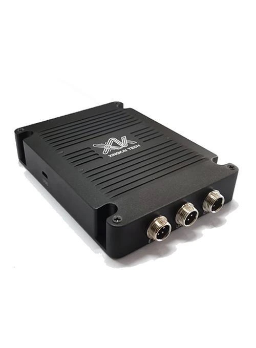
Single-housing appearance reference; robot-unit and receiving-unit quantities are specified in the quotation.
Compare different robot-side and receiving-unit housings for ground or surface-platform equipment.

Consider a transparent link with a UART TTL interface for IP-equipped endpoint devices.
Request a Configuration Quote for XK-304E
Tell us the video source, control interfaces, platform power supply and endpoint quantities for your XK-304E project. Xingkai checks the requested -100 configuration and provides an itemized radio and accessory quotation.